The annexed engravings illustrate a new process for bleaching and dyeing cotton and linen goods, invented by C. H. Metz, of Heidelberg, in Baden, Germany; it has recently been patented in France (being illustrated in the "Genie Industriel, " from which we have translated this), and all the important countries in Europe. The nature of the process consists in expelling all the air from the cotton goods or yarn, in an air-tight vessel, then the dyeing and bleaching liquid is allowed to flow through all the pored of the cotton, by hydraulic pressure, by which means cold liquors are made to answer as well as hot liquors, which are now employed n dyeing, and bleaching will be accomplished in much quicker time.
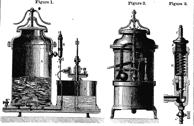
Fig. 1 is a vertical action of the apparatus. Fig. 2 is a side elevation of the same; fig. 3 is a sectional view of the spring gauge for indicating the pressure. The same letters refer to like parts.
The apparatus, as may be seen from fig. 1, consists of two vessels joined together on a cast-iron plate. In one of them, A, is placed the cotton to be dyed, and is merely a cylinder of wheet tin, or, preferably, of copper, firmly closed at the upper part by a lid, d, which is kept tight by the hand screw, I. The plate on which this vessel is fixed has several apertures, O, for the liquid to pass through, and is covered with a tin sheet of copper, C, every where perforated. A space is left between these two, the latter being supported on a circular rim and projection, q, and can be also taken up when required by means of the handle, p. The other vessel, B, which is smaller, is entirely open at the top, and has fixed on to it a pump, P, of which the piston can be workedb y hand or by any other movement. This pump is intended to draw up the liquid contained in the open vessel, B, and to send it by the pipe, n, into the closed vessel A; it is constructed in a similar manner to the injection pumps of hydraulic presses, and has at its base a pipe, the end of which is perforated to allow no extraneous substance to pass, and a safety-valve, x, as well as two other valves. At the upper part of the closed vessel is the piple, f, which forms one of the branches of a spring gauge, H; another branch, h, leading into the top of the vessel B. This gauge serves to show the pressude (fig. 3), it contains a conical valve, a', surmounted by sa poston, c', which passes through a socket, d, and has a circular base, e', to receive the pressure of the spring, f'. A screw cap, b', closes the top of the gauge, leaving in its cetre the necessary aperture for the vertical rod, l'. This rod, which forms part of the piston, c' is graduated at the upper part to show, in atmospheres, the degree of pressure existing in the apparatus when at work. From this arrangement it is easy to be understood that if, after having filled the vessel, A, with cotton on the one hand, and having placed in the vessel, B, on the other, a suitable quantity of water the pump, P, be put in motion, it will force the liquid from the open vessel, B, into the closed vessel, A, throught he perforations in the false bottom, C. Consequently the air contained in the fibres of the cotton being driven up by the liquid, rushes through the tube, f, into the gauge chamber. The gauge, therefore, serves at once as a regulator and indicator, because it only allows the liquid to go out when there is a sufficient pressure greater than that of the spring to open the valve (fig. 3). The liquid returns into the open vessel, B, by the pipe, h, the extremity of which does not extend quite to the surface of the water; it follows that the air which is expelled escapes upward, and the water can be again pumped into the closed vessel. There is a faucet, i' at the end of the indicator below the valve, to draw off any superfluous water, and another, u, at the end of the vessel, A, for inserting a manometer when required. There is also a faucet at the bottom of each vessel, for the purpose of emptying them.
In figure 1, a common hydrostatic pump is shown, with its weighted valve, S, and all the other parts. It is an invention for Bleach and Dye Works, more especially the latter, and is much better for the coloring of cotton in the wool, than in yarn or cloth. The valve, a, as it is acted upon by the compressed air, is lifted up until the air passes by the slots into the chamber, g', which allows it to pass off through the bent tube, h, as shown in fig. 1.
This apparatus is presented for more than one object; it is capable of being used to impregnate skins with tannin liquor, or it can be employed for impregnating hams, &c., with salt brine; or it can be employed on a large scale for extracting air from timber, and impregnating it with the sulphate of copper to Payenize it.

Ei kommentteja :
Lähetä kommentti